Control a ball on a plate using a robotic manipulator and a MPC controller. This project was carried out as part of the CS206B Robotic Manipulation and Interaction course at UC Berkeley
MPC Controller
MPC is a type of feedback control algorithm, in which a model of the system is used to make predictions about it’s future behavior. The control inputs are then computed based on the predictions, with the goal of achieving the desired system behavior. This is done iteratively, with the model being updated at each time step based on the measured system outputs.
![]()
The MPC design used is a Eulerian discretized model of general point-mass plate movement. The model does not take into account rolling ball dynamics, friction, or other external disturbances. While including this information may make the MPC more accurate in its predictions, feedback provided by monitoring the system would be able to correct for any major prediction error. A simplified version of the model’s provided states, system dynamics, and resulting output command are shown below.
\[ \begin{bmatrix} x \\ y \\ \dot{x} \\ \dot{y} \\ \theta \\ \psi \\ \end{bmatrix} \quad \rightarrow \quad \begin{cases} x_{k+1} = x_k + \dot{x}_k \Delta t \\ y_{k+1} = y_k + \dot{y}_k \Delta t \\ \dot{x}_{k+1} = \dot{x}_k - g \sin \theta_k \Delta t \\ \dot{y}_{k+1} = \dot{y}_k - g \sin \psi_k \cos \theta_k \Delta t \\ \theta_{k+1} = \theta_k + \dot{\theta}_k \Delta t \\ \psi_{k+1} = \psi_k + \dot{\psi}_k \Delta t \end{cases} \quad \rightarrow \quad \begin{bmatrix} \dot{\theta} \\ \dot{\psi} \\ \end{bmatrix} \]The MPC was tested against model-accurate and non-model accurate versions of a simulation environment. Even with cases such as 80% input, failing small-angle assumptions, or noisy position data, the MPC did a solid job at managing to reach desired positions and follow paths. A noisy simulation environment with reference tracking is shown below, with the red dot describing the desired position, grey dot as the simulated position of the ball, and the small markers indicating the MPC’s predicted future states.
![]()
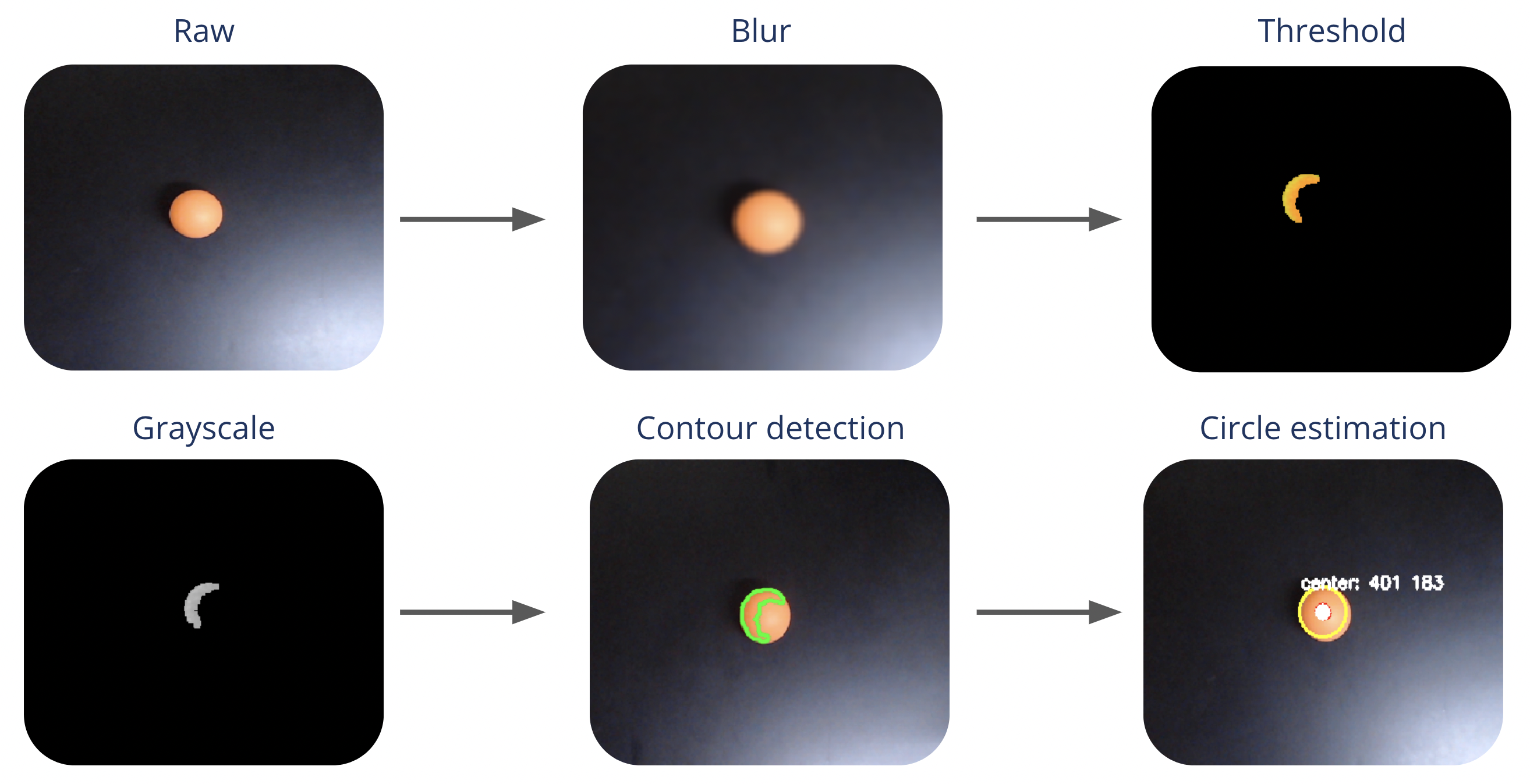
Ball Detection
The ball detection has been kept as lightweight as possible to used in real time. The process involves thresholding to separate the ball from the background, applying Gaussian blur to smooth edges, adding erosion and dilation to refine object boundaries, detecting contours to identify the ball, and estimating its centroid position.
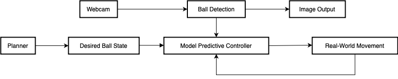
ROS Architechture
In a ROS-based system for controlling a robotic arm using ping pong ball coordinates, the architecture is structured into three modular ROS nodes:
- Sensor Node: Detects the ping pong ball using cameras and publishes its coordinates.
- Control Node: Receives the ball coordinates, calculates the necessary control inputs for the robotic arm’s position and orientation, and then publishes these inputs.
- Actuator Node: Receives control inputs and manipulates the robotic arm’s motors to achieve the desired position and orientation.
This setup enhances system flexibility and streamlines development, testing, and maintenance.
Results
The robot used is a Sawyer arm on which we attached a custom platform that hold the webcam and where the ball is balanced.